


Spare Parts Replacement — Operating Instructions
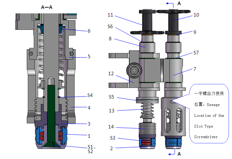
1. Change the Heating Head
Condition: the preform inner bore diameter changes.
Loosen the bolt S1 with an Allen key and prise off the preform unloading ring 4 with a flat screwdriver, then replace parts 1, 2, 3, 4 and 14.
2. Adjust the Cooling Water Pipes
Condition: the preform mouth outer diameter (Φd1) changes.
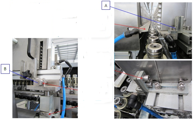
- Adjust the outer light box water channel: turn screw B.
- Adjust the inner light box water channel: loosen the screw A connected to the water channel.
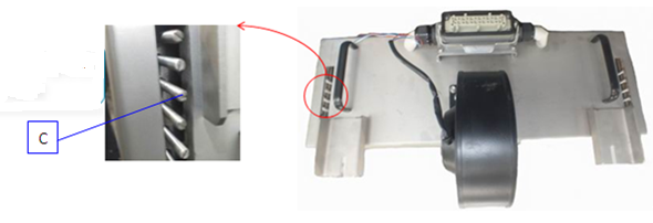
- Adjust the distance between the lamp and the preform: turn the screw at C.
3. Replace the Infrared Lamp
Lamp replacement steps:
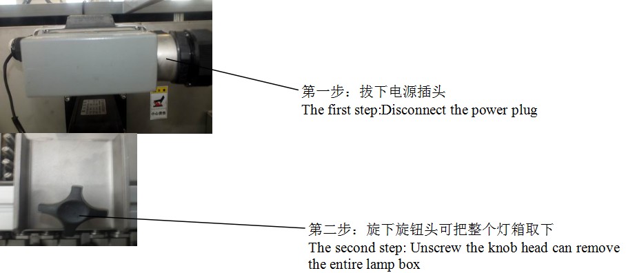
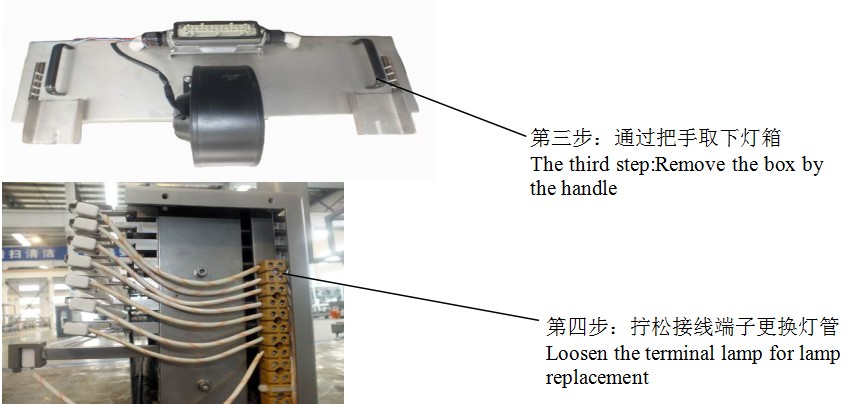
Finally, put the light box back to its original position, tighten the handle and plug in the power plug.
4. Change the Blowing Nozzle
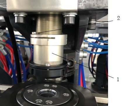
Condition: the preform mouth outer diameter (Φd1) changes.
Loosen the screw (2) and take out the sealing head (1).
Change to a new blowing nozzle and adjust the height of the nozzle to meet the requirements.
Tighten the screw (2).
5. Change the Bottle Discharge Dial
(1) Replace the transition dial
Loosen the bolt (A), take down the dial (6) and take down the adjusting pole (5). Exchange for the dial that suits the bottle type, fit it on and tighten the bolt.
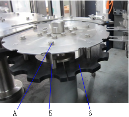
(2) Adjust the height of the bottle guard pole
Loosen the bolt (A) and take down the pole (5). According to the bottle height, exchange for the appropriate pole and tighten the bolt (A).
Note: please adjust the parameters after changing the parts (heating, blowing, etc.).
If you need technical support, please consult the engineers of King Machine.


