


Summary
By using this guide, each component on the machine can be identified, the parts that are prone to wear and their replacement times can be checked, and the installation data required for the workshop can be obtained before the production line arrives. All the following part numbers correspond to the disassembly diagrams in the corresponding chapters of the manual. The replacement cycle is based on normal operating conditions; when the machine operates in harsh environments, please shorten the replacement cycle.
All part numbers mentioned below refer to the exploded drawings of the corresponding chapters in the manual. Replacement intervals are based on normal operating conditions; shorten them when the machine runs in a harsh environment.
-
Structure & function
The 11 main assemblies of the machine - heater, rotary unit, transfer arm, mould support unit, distributors and more - with their working principles.
-
Vulnerable parts
Every wear part of each sub-assembly with its replacement interval, e.g. O-rings, springs and high-pressure valve repair kits.
-
Technical data
Capacity, bottle range, power, air and water consumption, plus the installation requirements for space, floor, environment and media quality.
XC8-00 Operation Manual - Structure & Technical Data
Download PDF · Chapter D-E · 6 MB
Equipment Structure & Function
The XC8 machine consists of 11 main assemblies. Each assembly below links to its own technical article - click a part row to locate the corresponding disassembly section of the manual.
Main assemblies overview
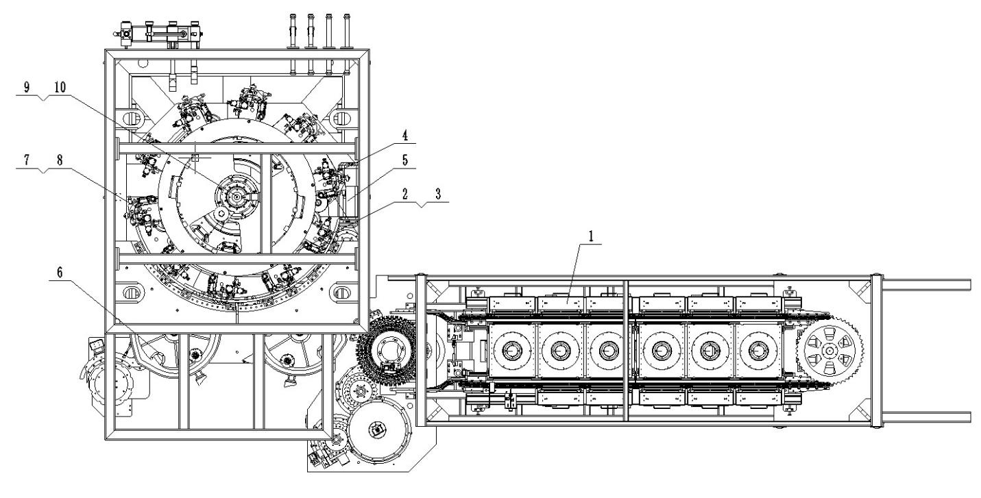
| No. | Assembly | Function |
|---|---|---|
| 1 | Heater | Infrared oven with 9 heating boxes; rotates preforms 360° for even heating. |
| 2 | Mold base rail | Guides the bottom mould up / down in sync with mould opening and closing. |
| 3 | Mold opening / closing rail | Controls mould open & close positions, synchronised with preform feed and bottle discharge. |
| 4 | Rotary part | Main rotary unit carrying the mould stations around the machine axis. |
| 5 | Driving system | Reducer motor, synchronous belts and brake - drives all rotary motions. |
| 6 | Transfer arm | Robot arm transferring preforms from the heater into the moulds. |
| 7 | Mold support unit | Mould frame with clamping mechanism and mould compensation device. |
| 8 | Tensile mechanical sealing device | Stretching rod + sealing cylinder: stretches the preform and seals the mould neck. |
| 9 | Oil distributor | Distributes lubrication oil to the rotating stations. |
| 10 | Air distributor | Routes high / low pressure blowing air to every mould via the rotary unit. |
| 11 | Central lubrication system | Programmed automatic greasing of rails, cams and bearings. |
1. Heater
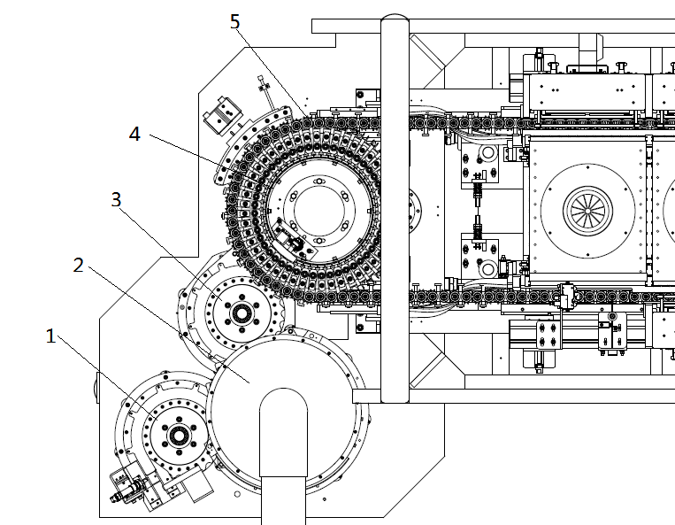
Preforms pass through 9 infrared ovens on heating heads that self-rotate via a chain drive, so every side of the preform is heated evenly. PLC + HMI control the lamp voltage layer by layer; air and water cooling protect the bottle neck from re-heating.
| # | Part | Function / remark | Service life |
|---|---|---|---|
| 1 | Heater module (heating head) | Expansion chuck holds the preform and rotates it in the oven. | - |
| 2 | Heating module (oven) | 9 boxes × 9 lamps each, multi-zone infrared heating. | - |
| 3 | Bearing 9 + O-ring S3 | Wear parts of the heating head rotary unit. | 1 year / 5,000 h |
| 4 | Spring 13 | Chuck return spring inside the heating head. | 7,500 h |
| 5 | Deduster device (ion nozzle) | Ionised air removes static dust inside preforms; clean the nozzle weekly. | Clean weekly |
2. Mould opening / closing rail
The rail controls mould open & close positions synchronised with preform feed and bottle discharge. Closing rail II is movable: if a mould is not fully closed, the swing-arm bearing pushes the rail, the sensor detects it and the PLC stops the machine immediately.
| # | Part | Function / remark | Service life |
|---|---|---|---|
| 1 | Rail seat / opening rail | Fixed guide body of the mould opening / closing mechanism. | - |
| 2 | Closing rail II | Movable rail with safety detection function. | - |
| 3 | Bushing / swing-arm bearing | Sliding and rolling elements of the rail system. | Lubricated by central system |
| 4 | Sensor 7 | Detects "mould not closed" and triggers emergency stop. | - |
| 5 | Spring 8 | Returns the movable closing rail. | - |
3. Driving system
The drive train consists of a reducer motor, synchronous belts and pulleys, an air-operated disc brake and a slew bearing. Tension wheel seats keep every synchronous belt at the correct tension; check belt tension during every monthly maintenance.
| # | Part | Function / remark | Service life |
|---|---|---|---|
| 1 | Main motor + reducer | 7.5 kW main drive of the rotary unit. | - |
| 2 | Synchronous belts | Drive heater, transfer arm, preform infeed and bottle discharge units. | Inspect monthly |
| 3 | Air disc brake | Positions and holds the rotary unit during stop. | - |
| 4 | Tension wheel seats | Keep belt tension of each transmission branch. | - |
4. Mould support unit & stretching sealing device
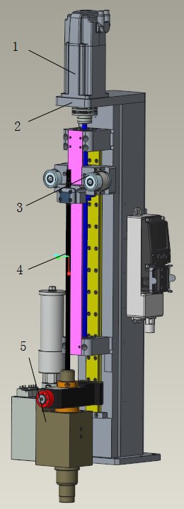
The mould frame opens and closes along the rails; a compensation air circuit (40 bar) presses the mould halves together for a thin parting line. The stretching electric cylinder drives the stretching rod, the sealing cylinder seals the bottle neck during blowing.
| # | Part | Function / remark | Service life |
|---|---|---|---|
| 1 | Bottom mould spring 4B | Buffers the bottom mould when it rises. | 1 year / 5,000 h |
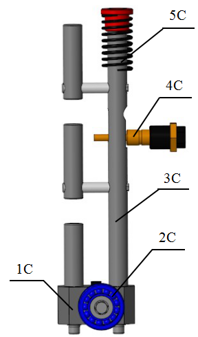
| 2 | Locking spring 5C | Mould clamping / unlocking mechanism return spring. | 1 year / 5,000 h |
| 3 | Compensation sealing ring 3 | Seals the 40 bar mould compensation air circuit. | Replace at once if damaged |
| 4 | Stretching electric cylinder | Grease sliding parts every 6 months; check operation after reassembly. | Seals: 1 year |
| 5 | Sealing cylinder + HP valve | Seals the preform neck and introduces high-pressure air. | Seals: 1 year |
5. Distributors, air piping & central lubrication
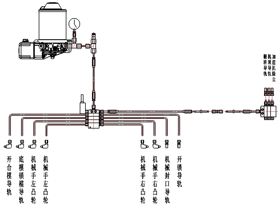
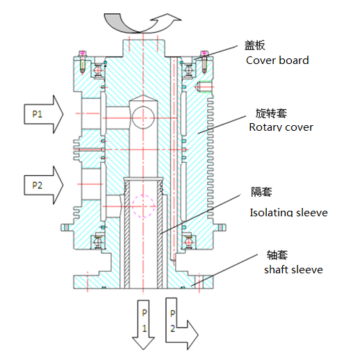
The air distributor routes high / low pressure air through the rotary unit to every mould (slip ring, encoder, air tank, distributing blocks). The central lubrication system greases rails and cams by program; the oil pump is filled with Shell Alvania EP2 grease.
| # | Part | Function / remark | Service life |
|---|---|---|---|
| 1 | Conductive slip ring | Transmits all control signals to the rotating electrical components. | - |
| 2 | Encoder | Tracks every mould station and syncs the sequence of all actuators. | - |
| 3 | Air tank + relief valve | Stores low-pressure blowing air and keeps pressure stable. | - |
| 4 | HP valve repair kit | Seal kit of the high-pressure valve group; close P1 / P2 / PAS and discharge before replacing. | Per maintenance plan |
| 5 | Single-point lubricators | Feed sealing / unlocking / heater rails automatically. | Replace every 6 months |
| 6 | Grease - Shell Alvania EP2 | Standard grease of the central lubrication pump. | Top up per plan |
Technical Data
Basic parameters of the XC8-00 blow moulding line and the installation requirements for space, floor, environment, compressed air and cooling water. Final data always refer to the nameplate of your machine.
Basic technical parameters
| Item | XC8-00 |
|---|---|
| Capacity | 19,200 BPH |
| Bottle volume | 0.25 - 2.5 L |
| Max. bottle diameter / diagonal | 115 mm |
| Max. bottle height | 340 mm |
| Preform material | PET |
| Preform internal diameter | Φ14 - Φ26 mm |
| Preform height | 150 mm |
| Supporting ring diameter | ≤ Φ36 mm |
| Cavity number | 8 |
| Main driven motor power | 7.5 kW |
| Voltage / frequency / phase | 380V±10% / 50Hz / three phase + grounding wire |
| Heating oven quantity | 9 |
| Lamp quantity of each oven | 9 rows |
| Lamp power | 3 / 2.5 kW |
| Installation power | 285 kW |
| High pressure compressed air | 3.5 MPa, food-grade pure gas (clean, dry, oil free) |
| Cooling water pressure | 6 ± 0.5 bar |
| Cooling water - blow molder | 5 m³/h (water temperature 20 - 40 °C) |
| Cooling water - heater | 2.5 m³/h (7 - 12 °C) / 2.5 m³/h (17 - 22 °C) |
| Machine weight | Blow molder 14 t + heater 4 t |
Installation & environment requirements
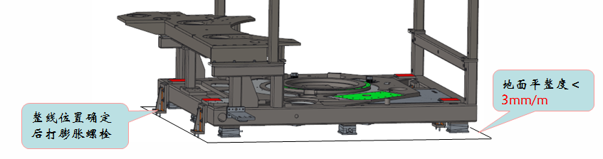
- Minimum working and maintenance space: footprint 12 × 9 m, height 5 m (excluding transport and lifting space).
- Floor: C30 steel-reinforced concrete, 300 mm thick; epoxy resin floor paint, floor drains at the lowest points.
- Temperature 24 ± 2 °C (min 15 °C, max 35 °C); humidity 60 - 70%.
- Air cleanliness class 100,000; dust-free, mould-proof, moisture-proof and shock-proof blowing room with fresh-air filtration.
- Install proper ventilation above the heating oven to keep the thermal balance of the system.
- Blowing room door: curtain or air curtain to separate from other rooms; wall tiles up to 1.2 m; lighting approx. 300 W per 6 × 6 m.
Compressed air & cooling water quality
Compressed air piping must be purged clean for at least 2 hours before connection and use stainless seamless steel pipes; pressure fluctuation ≤ ±0.1 MPa; a terminal filter is recommended at the machine air inlet (GB/T 13277.1-2008).
| Substance in compressed air | Class | Max. value |
|---|---|---|
| Solid particles | ≤ 1 | 0.1 μm / 0.1 mg/m³ |
| Water | ≤ 4 | Pressure dew point 3 °C |
| Oil | ≤ 1 | 0.01 mg/m³ |
| Cooling water item | Requirement |
|---|---|
| Water standard | Drinkable water standard, no impurity / pollution, reusable |
| PH value | 7 - 8 |
| Carbonate hardness (CaCO₃) | < 140 mg/L |
| Mechanical impurity | None |
| Pollutant particle size | ≤ 0.1 mm |
| Additive | Suitable antifreeze / preservatives |


